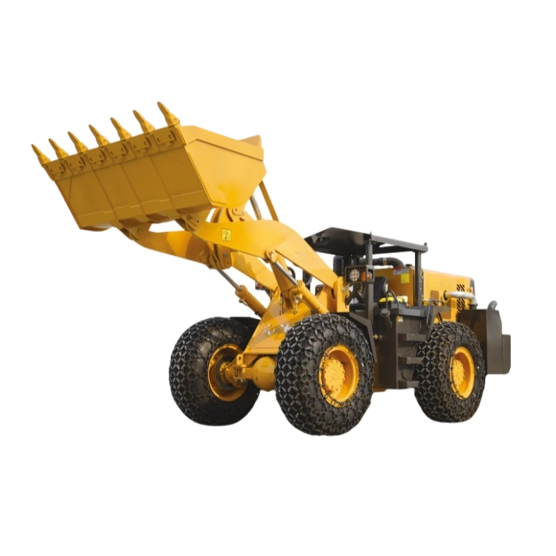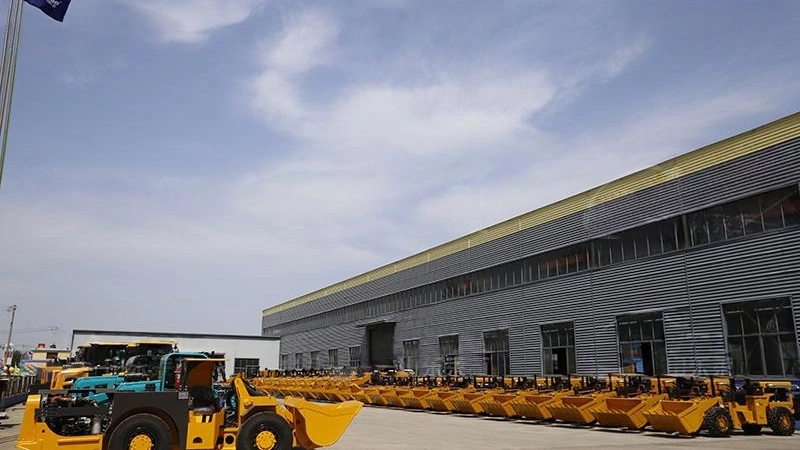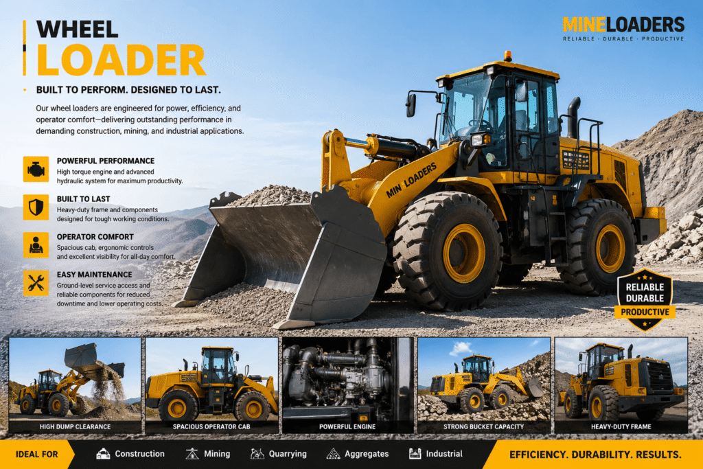
The modern wheel loader is a marvel of modular engineering, designed to balance raw power with surgical precision. Whether operating in a high-volume quarry, a complex construction site, or a precision-heavy industrial facility, the synergy between its various subsystems dictates its total cycle time and operational lifespan. Understanding the primary wheel loader components is not merely an academic exercise; it is essential for maintenance engineers, OEM project managers, and site supervisors who must optimize fleet uptime.
Unlike simpler earthmoving equipment, the wheel loader utilizes an articulated steering system and a high-pressure hydraulic circuit to achieve its versatility. This guide breaks down the complex anatomy of these machines, providing technical insight into the systems that drive their performance.
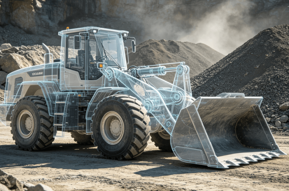
The Structural Backbone: Chassis and Articulation
At the core of every wheel loader is its chassis, typically divided into two main sections: the front frame and the rear frame. These are joined by an articulation joint, which allows the machine to pivot.
- Front Frame: Specifically engineered to handle the torsional stresses of lifting. It houses the lift arms (linkage) and the attachment.
- Rear Frame: Designed to provide a stable counterweight. It houses the engine, transmission, and cooling systems.
- Articulation Joint: This hinge consists of two heavy-duty pins and bearings. It allows the loader to turn in tight radiuses, which is a significant advantage over rigid-frame loaders.
In heavy-duty applications, these frames are constructed from high-strength, low-alloy steel to withstand the impact of loading dense materials like granite or recycled concrete.
The Powertrain: Generating and Transferring Torque
The powertrain is the “heart” and “muscle” of the machine. It transforms chemical energy from fuel into the mechanical torque required to push into a pile of material.
- Diesel Engine: Modern loaders typically utilize turbocharged, Tier 4 Final or Stage V compliant diesel engines. These engines are optimized for high torque at low RPMs, a necessity for the “crowding” phase of the loading cycle.
- Transmission: Most medium-to-large wheel loaders use a powershift transmission. This allows for seamless gear changes under load. In some compact models, hydrostatic transmissions are used for smoother speed control and better fuel efficiency during light-duty tasks.
- Axles and Differentials: To ensure traction on unstable ground, wheel loaders utilize heavy-duty axles. Many are equipped with limited-slip or locking differentials to prevent tire spin, which reduces tire wear and improves fuel economy.
The Hydraulic System: The Fluid Power Circuit
If the engine is the heart, the hydraulic system is the nervous system that translates power into movement. This system manages the lifting, tilting, and steering functions.
- Main Hydraulic Pump: Often a variable-displacement piston pump. It adjusts fluid flow based on the operator’s demand, ensuring that power isn’t wasted when the machine is idling or performing light tasks.
- Control Valves: These act as the brain of the hydraulic circuit, directing high-pressure oil to the appropriate cylinders. Modern systems often use “load-sensing” valves to prioritize steering over bucket movement for safety.
- Hydraulic Cylinders: These are the actuators. Double-acting lift cylinders raise the boom, while tilt cylinders (often arranged in a “Z-bar” linkage) provide the breakout force necessary to dig into compacted material.
| Component | Function | Technical Highlight |
| Z-Bar Linkage | Tilts the bucket | Optimized for maximum breakout force at ground level. |
| Parallel Linkage | Keeps the load level | Preferred for pallet handling and fork applications. |
| Variable Pump | Supplies fluid | Reduces parasitic engine load, improving fuel efficiency by up to 15%. |
The Electrical Architecture and Signal Integrity
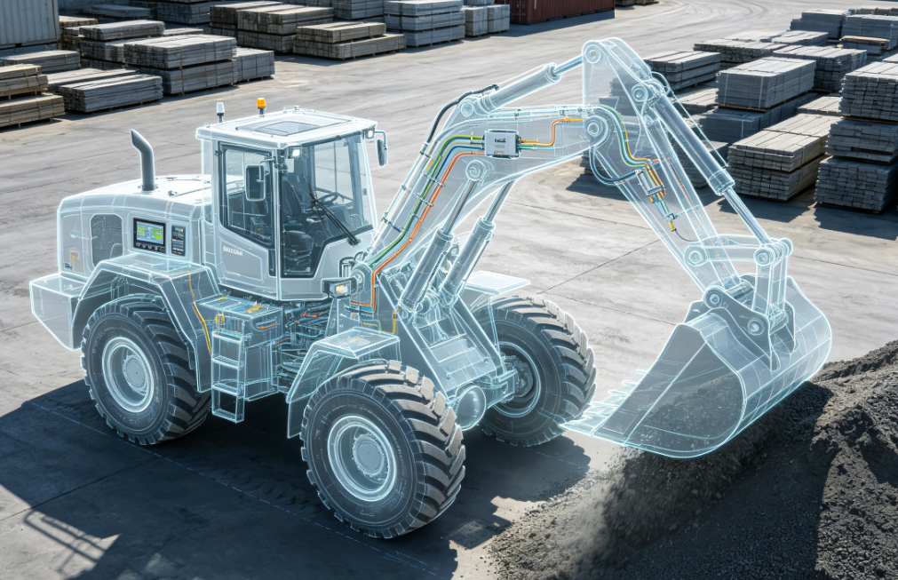
As wheel loaders transition toward “smart” functionality—incorporating telematics, automated bucket leveling, and payload weighing systems—the electrical system has become as critical as the engine. This architecture relies on a complex network of sensors and Electronic Control Units (ECUs) communicating via CAN-bus protocols.
In the harsh environments where wheel loaders operate, electrical failure is often caused by vibration, moisture, or thermal cycling. High-quality electrical connectivity is the primary safeguard against these failures. Engineers must specify industrial-grade connectors and cabling systems that can maintain signal integrity despite constant 24/7 mechanical stress.
Ruggedized connectors are utilized for:
- Engine Control Modules (ECM): Managing fuel injection and emissions.
- Hydraulic Solenoids: Translating electronic joystick movements into fluid flow.
- Telematics Gateways: Sending real-time health data to fleet managers.
Using standardized, high-reliability connectors ensures that the machine remains operational in sub-zero temperatures or high-dust mining environments, where a single lost signal can lead to a complete system “limp mode” event.
The Operator Station: Ergonomics and Control
The cab of a wheel loader is designed for long-shift productivity. Beyond the ROPS/FOPS (Roll-Over/Falling Object Protective Structure) safety certifications, the focus is on the Human-Machine Interface (HMI).
- Joystick Controls: Many modern loaders have replaced traditional steering wheels and levers with integrated joysticks. These use electro-hydraulic actuators to reduce operator fatigue.
- Monitoring Displays: Real-time displays provide data on fluid temperatures, fuel levels, and diagnostic codes.
- Climate Control: High-capacity HVAC systems are essential, as the glass-heavy design of cabs can create significant heat gain in summer environments.
The Working Tool: Buckets and Attachments
The versatility of a wheel loader is ultimately defined by its attachment. The “bucket” is the most common, but it is far from the only option.
- General Purpose Bucket: Designed for dirt, gravel, and sand.
- Rock Bucket: Features a reinforced “spade nose” and wear-resistant liners for abrasive mining applications.
- Light Material Bucket: Larger volume for handling snow, mulch, or grain.
- Quick Coupler: A hydraulic locking mechanism that allows the operator to switch between a bucket and pallet forks or a grapple without leaving the cab.
FAQ
What are the most common wear-parts on a wheel loader?
The most frequent wear-parts include Bucket Teeth (Get/Ground Engaging Tools), cutting edges, hydraulic seals, and the articulation pins. Additionally, tires are a significant operational cost, particularly in rock-handling applications.
Why is “Breakout Force” important in wheel loader specs?
Breakout force is the maximum upward force the machine can exert using the bucket’s tilt cylinders. It determines the machine’s ability to penetrate and lift heavy, compacted material. It is a key metric for matching a loader to a specific application (e.g., quarrying vs. landscaping).
How do electro-hydraulic controls differ from manual controls?
Manual controls use physical linkages or pilot oil lines to move valves. Electro-hydraulic controls use electronic signals to move the valves. This allows for programmable features like “return-to-dig” and “kick-out” heights, which automate repetitive tasks and improve cycle times.
What is the role of the counterweight in a wheel loader?
The counterweight is located at the extreme rear of the machine. It balances the weight of the load in the bucket. Without a properly sized counterweight, the machine would lose rear-axle traction and become unstable during high-lift operations.
How does the articulation angle affect performance?
Most loaders have an articulation angle of approximately 40 degrees. A wider angle allows for better maneuverability in tight spaces but requires a more robust steering hydraulic circuit to maintain stability when the machine is fully articulated under load.
Reference Sources
- SAE International (Society of Automotive Engineers): Standards for J1116 – Categories of Off-Road Self-Propelled Work Machines. sae.org
- ISO 6165: Earth-moving machinery — Basic types — Identification and terms and definitions. iso.org
- Association of Equipment Manufacturers (AEM): Technical reports on construction equipment safety and structural integrity. aem.org
- IEEE Xplore: Research on CAN-bus reliability and electronic sensor integration in heavy machinery. ieee.org