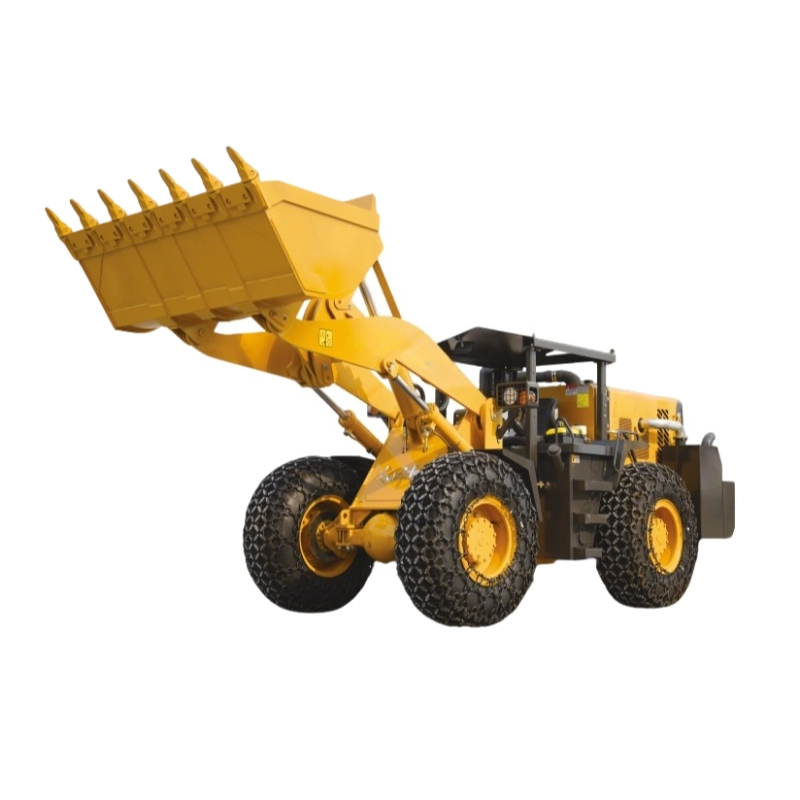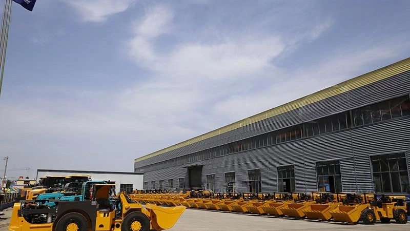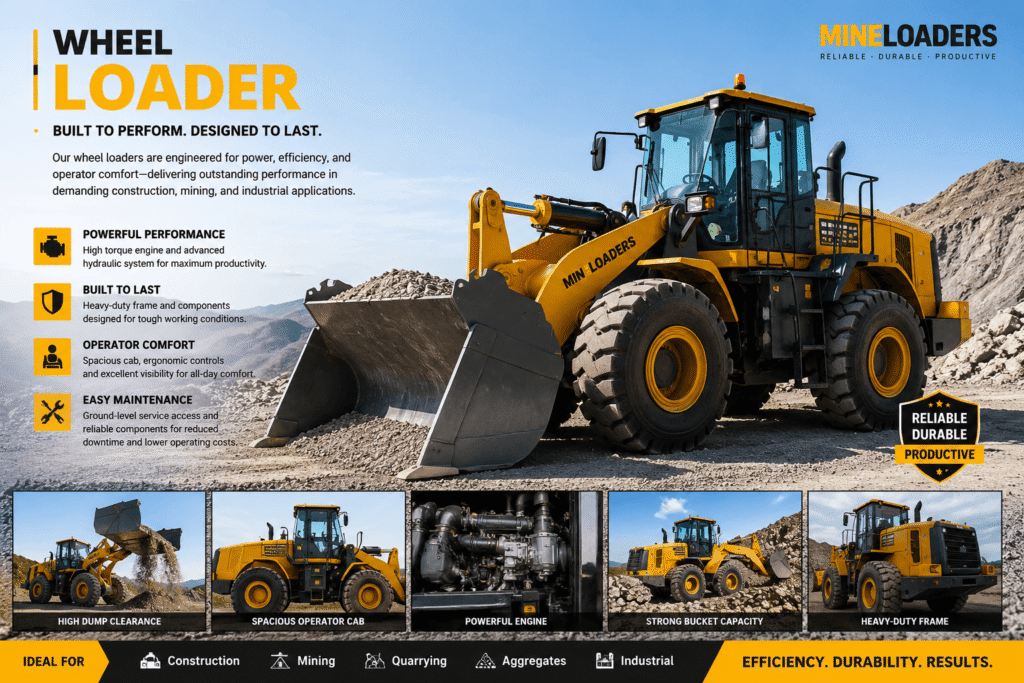
The front wheel loader is the workhorse of modern infrastructure, designed to move massive volumes of material with precision and speed. At its core, the efficiency of this machine depends on the synergy between its mechanical, hydraulic, and structural systems. Understanding these components is essential for fleet managers, heavy equipment operators, and engineers looking to optimize duty cycles and machine longevity.
Unlike rigid-frame vehicles, a wheel loader relies on a sophisticated articulated architecture. This design allows for a tight turning radius while maintaining the stability required to lift multi-ton payloads.
The Core Architecture: Articulated Chassis and Frame
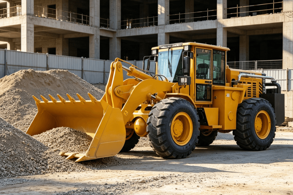
The structural backbone of a wheel loader is its two-part articulated frame. This chassis consists of a front frame and a rear frame, connected by a heavy-duty center pivot pin.
In this configuration, the front frame supports the lift arms (boom) and the bucket, while the rear frame houses the engine, transmission, and operator cab. Steering is achieved by hydraulic cylinders that pivot the entire front section relative to the rear. This design is superior for job sites with limited space because the wheels follow the same path during a turn, significantly reducing tire wear and ground disturbance.
Engineering for durability in the frame involves high-tensile steel and robotic welding to manage the stress of “breakout force”—the maximum upward force the loader can exert.
The Powertrain: Converting Fuel to Torque
The drivetrain is responsible for moving the machine and powering its work-tools. It is a complex assembly that manages high torque at low speeds.
- Diesel Engine: Typically a turbocharged, Tier 4 or Stage V compliant engine. It provides the raw horsepower needed for both propulsion and hydraulic pressure.
- Torque Converter: Acts as a fluid coupling between the engine and the transmission. It allows the loader to crowd a pile of heavy material without stalling the engine.
- Power Shift Transmission: Allows the operator to change gears under load, ensuring smooth transitions during the “V-cycle” loading pattern.
- Planetary Axles: Located at the wheel hubs, these provide final gear reduction. This minimizes the stress on the driveshafts by multiplying torque at the wheel rather than in the gearbox.
Hydraulic Systems: The Mechanical Muscles
Without hydraulics, a wheel loader is simply a tractor. The hydraulic system consists of pumps, valves, and cylinders that convert engine power into mechanical movement.
The primary lift cylinders control the boom’s vertical movement, while the tilt cylinder (often connected via a Z-bar linkage) manages the bucket’s angle. The Z-bar linkage is the most common configuration in construction due to its high breakout force and excellent visibility to the bucket edges.
Modern loaders, such as those utilized in specialized environments like underground mining, often integrate variable displacement pumps. These pumps adjust hydraulic flow based on demand, reducing fuel consumption and heat buildup in the system.
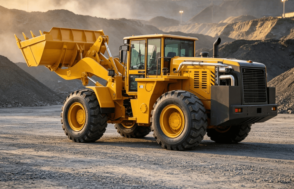
Front-End Attachment Components
The “front” of the wheel loader is defined by its work-tools. While the bucket is the standard attachment, the structure is designed for versatility.
| Component | Function | Maintenance Priority |
| Lift Arms (Boom) | Provides the reach and height for dumping into trucks. | Inspect pivot pins for lubrication. |
| Z-Bar Linkage | Translates hydraulic force into bucket tilt/breakout. | Check for cracks in stress points. |
| Quick Coupler | Allows for rapid switching between buckets, forks, or grapples. | Ensure locking pins are fully engaged. |
| Bucket Teeth/Edges | The primary contact point with abrasive materials. | Replace wear parts before the base metal erodes. |
The Operator Station: Safety and Control
The cab, or Operator Station, is engineered for both ergonomics and survival. In the heavy equipment industry, the structural integrity of the cab is governed by two critical standards:
- ROPS (Roll-Over Protective Structure): Designed to protect the operator if the machine tips.
- FOPS (Falling Object Protective Structure): Essential for mining and demolition, protecting the operator from overhead hazards.
Inside, the use of pilot-operated joysticks or “fly-by-wire” electronic controls has replaced old mechanical levers. This reduces operator fatigue and allows for features like “return-to-dig,” which automatically resets the bucket to the optimal loading position.
Engineering for Extreme Environments
While standard wheel loaders are built for surface construction, certain industrial applications require specialized structural modifications. In underground mining, for instance, loaders (often referred to as LHD – Load, Haul, Dump) must feature low-profile designs and reinforced frames to withstand falling rock and confined spaces.
Manufacturers like Mineloaders focus on these high-stress structural requirements, ensuring that components such as the oscillation joint and exhaust scrubbing systems are optimized for subterranean safety and durability. Whether on the surface or underground, the fundamental mechanical logic remains the same: a balance of weight distribution, hydraulic flow, and structural rigidity.
FAQ
What is the difference between a wheel loader and a backhoe?
A wheel loader is a dedicated material mover with a front-mounted bucket and an articulated frame for heavy lifting. A backhoe is a rigid-frame tractor equipped with a front loader bucket and a rear-mounted digging arm (hoe). Loaders generally have much higher lift capacities and bucket volumes.
What is “Breakout Force” in wheel loader specifications?
Breakout force is the maximum upward vertical force exerted by the bucket, measured at the tip of the cutting edge. It determines the machine’s ability to penetrate and lift heavy, compacted material from a pile.
Why is articulation important for wheel loader components?
Articulation allows the machine to pivot in the center. This provides a smaller turning radius and allows the front and rear wheels to track in the same path, which is critical for stability when carrying heavy loads and for reducing tire scuffing on hard surfaces.
How often should hydraulic filters be replaced?
While it varies by manufacturer, a standard interval is every 500 to 1,000 hours. However, in high-dust environments or heavy-duty cycle applications like mining, oil analysis should be used to determine if more frequent changes are required to protect sensitive valves and pumps.
Reference Sources
- ISO 3471: Earth-moving machinery — Roll-over protective structures — Laboratory tests and performance requirements. iso.org
- SAE J1040: Performance Criteria for Rollover Protective Structures (ROPS) for Earthmoving, Construction, Logging, and Agricultural Machines. sae.org
- Association of Equipment Manufacturers (AEM): Technical reports on drivetrain efficiency and safety standards. aem.org