Mining loader attachments should be matched to the material and the complete loader configuration. A bucket, fork or clamp can fit the mounting points yet exceed a capacity limit or need unavailable hydraulic flow. Physical connection is the start of compatibility, not the end.
The first question is practical: what must the tool pick up, carry and release? Loose aggregate, fragmented rock and individual blocks behave differently. The attachment should solve that task without creating a new problem in reach, visibility or load control.
What changes when a loader attachment changes?
Attachment mass and load position influence the working machine. A longer tool moves the load farther forward, while a heavier tool changes the mass carried ahead of the axle. The loader’s bucket payload rating cannot automatically be applied to forks or clamps.
Hydraulic tools add another set of conditions. Required flow, pressure, return arrangement and controls must match the loader. A connection point alone does not establish continuous hydraulic capability for the intended tool.
| Attachment | Typical task | Main compatibility question |
| General material bucket | Loose aggregate or prepared material | Does volume suit density and rated payload? |
| Reinforced rock bucket | Abrasive or fragmented rock | Are tool mass and wear arrangement approved? |
| Approved light-material bucket | Lower-density loose material | Does additional volume preserve clearance and capacity? |
| Fork assembly | Palletized or defined unit loads | What capacity applies at the actual load center? |
| Stone clamp | Handling individual blocks | Does geometry suit the block and approved holding force? |
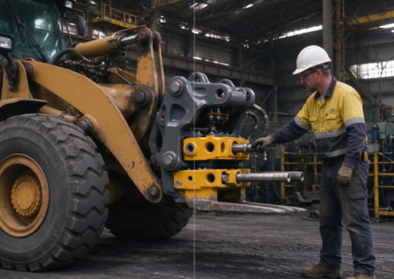
Quick couplers also become part of the capacity and geometry assessment. Include their mass, offset and retention method. An adapter that resolves the mounting interface can still change reach or introduce interference.
Caterpillar’s wheel-loader selection guidance likewise treats coupler and hydraulic compatibility as selection factors. Its equipment specifications do not transfer to other machines. Apply the same complete-configuration approach to the loader being evaluated.
Bucket applications for abrasive rock and loose material
For loose material, begin with bulk density and the expected filling pattern. A bucket can run out of volume before reaching rated payload, or reach the payload limit while partly filled. The mining loader capacity guide explains that relationship in more detail.
Fragmented rock brings a different restriction. Large pieces may bridge across the opening, leaving unused space behind them. Increasing the stated bucket volume does not necessarily improve entry into the pile.
Match wear protection to the observed damage. Floor abrasion, sidewall contact and tooth damage are different mechanisms. Added plate should protect the relevant area without making the tool unnecessarily heavy.
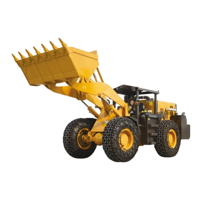
The LT633 listing describes teeth and wear-resistant bottom plates on its reinforced bucket. That supports the named configuration, rather than any larger aftermarket bucket. Confirm the complete attachment when the volume or protection package changes.
ESCO’s LHD bucket documentation distinguishes rock, mechanical and ejector designs. It also connects wear packages with site conditions and component replacement. This illustrates why bucket design includes discharge and maintenance access, not just cubic metres.
For sticky material, inspect what remains after dumping. Carryback reduces useful volume on the next pass and can prolong the cycle. A suitable profile and discharge method may matter more than increasing bucket size.
Forks and stone clamps in mine support work
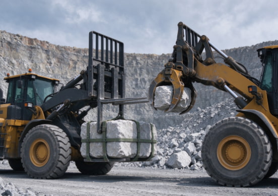
Forks are useful for defined unit loads where the loader-and-fork arrangement is approved. The relevant capacity depends on the actual load center. A pallet’s overall weight is insufficient without knowing where its center of gravity sits.
Long or uneven loads can shift that center forward or sideways. Check the load’s shape, support and retention method. Treat these as part of the handling task rather than assuming a bucket rating covers them.
Stone clamps need a separate assessment of block shape, contact surfaces and orientation. An adequate opening does not establish adequate holding capability. The load must remain controlled throughout pickup, travel and placement.
The LT656 product page lists forks and stone clamps among its working devices. Detailed capacity, hydraulic and interface information still needs to match the selected attachment. One model’s available tools are not a universal fitment list.
Check the intended work area as well. A clamp may accommodate the block in an open yard but lack positioning room beside a truck. Tool width, hose movement and load position can also change the operator’s view.
For equipment that changes tools frequently, retention checks need to remain practical. Use the manufacturer’s procedure for the exact coupler. Convenience does not replace a verified locking arrangement.
How to check mining loader attachment compatibility
Review the interfaces in a useful order: connection, capacity, hydraulics, working envelope and maintenance. A resolved mounting question should not hide an unresolved load or oil-flow requirement. Keep the evidence tied to the installed arrangement.
For a proposed attachment, obtain:
- Tool mass and center-of-gravity information.
- Mounting dimensions or the approved coupler interface.
- Capacity at the relevant load center and working position.
- Hydraulic requirements, including return conditions where applicable.
- Drawings showing transport, working and discharge positions.
- Wear-part identification and access for inspection or replacement.
Check hoses through the full range of articulation and attachment movement. A hose that looks clear with the machine straight can become trapped during turning. Guards and adapters belong in that envelope check too.
For an attachment with sustained hydraulic demand, assess the loader’s documented continuous-duty capability. A peak pressure or momentary flow figure may not describe sustained operation. Cooling and control requirements should be resolved with the machine and attachment documentation.
The acceptance review should identify both the loader and tool, including relevant revisions. Confirm the approved capacity and retention arrangement, then check interference through an appropriate supervised procedure. Record any limits operators need to understand when changing tools.
Use the mining loader range to identify the base machine before comparing optional tools. The useful attachment is the one that fits the material, machine and work area together. Extra versatility has value only when those interfaces are resolved.
FAQ
Will a bigger bucket always move more material per hour?
No. Density, tool mass, filling, discharge and maneuvering can limit the benefit. The approved loader-and-bucket capacity remains the governing limit.
Can forks use the bucket’s rated payload?
Do not assume so. Obtain the capacity for the complete fork arrangement at the actual load center.
Does a hydraulic quick coupler prove the tool is compatible?
No. It addresses the connection, while capacity, geometry and hydraulic requirements still need assessment. Use the approved attachment-retention procedure.